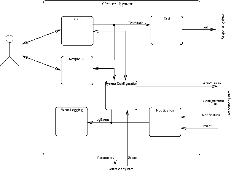
Figure 2.1 Control System Block Diagram
The control system is reponsible for interaction of the HMS with human users and external systems (e.g., security service provider computer systems). It is implemented in software on both the XMAD card and the PC and also includes the keypad and LCD display.
This is where you should describe the external interfaces of this block (i.e., how dos it interact with the environment in which it exists). Every line that crosses the boundary of the block should be described.
The control system provides two interfaces suitable for human users: on the keypad and LCD, and a Graphical User Interface (GUI) on the PC, as described below. It also provides a software interface in the XMAD software via which it receives event descriptions and instructions to send notification of a threat.
The Control System interacts with the response and detection systems via the software interfaces defined in the respective sections. It may also send notifications to external systems via SMTP (e-mail) or a modem, if configured.
void event(EventType type, int sensorId)type is the type of event, as defined in Table 2.1. sensorId is
the unique identifier associated with the relevant sensor.
| Type | Interpretation |
|---|---|
DigitalValue | A digital sensor state has changed. |
AnalogThreshold | An analog sensor has crossed its threshold value. |
| ... | ... |
void notification(AlertType reason, int sens[], int n)reason is the class of alert.sens[] is an array of sensor ids indicating which sensors are
involved in the alert.n is the number of elements in sens.
The control system is further sub-divided into the following functional components, as illustrated in Figure 2.1.
In a complete document, the details of the interfaces (i.e., a precise description of every internal line in the figure) and internals of each of the following should be given, either in the sections below or in separate chapters. For primarily software systems a UML class diagram would be an appropriate alternative to this block diagram.
The keypad UI is responsible for presenting information on the LCD and interpreting commands from the keypad.
Describe the detials of the interaction between the keypad UI and the System Configuration
The GUI is responsible for presenting a graphical representation of the monitor system on the PC software through which a user can complete all system configuration, operation, interogation and test tasks.
Responsible for formulating a message with appropriate address information and textual description of an alert situation and passing that on through the configured external interface (e.g., e-mail, phone).
Responsible for storing the system configuration information and for passing on the appropriate parts of this configuration to the response and detection systems.
Responsible for maintaining a log of all system events, with timestamps and textual description.
Provides functions for invoking tests of subsystems.